

B-SIM V2.5 Reference - Blow molding simulation

Parison extrusion
optimization example #1
PWT control optimization
Optimized project details
In this example, a specially designed mold is used for blow molding. See below the used tools and the simulation results with all PWT settings at 50% (initial, "neutral" position). No other extrusion control is used (AWT settings are at 50%, SFDR is at the neutral position too).
For PWT1 and PWT2 in the neutral position, the extruded parison has everywhere the same thickness ( in this case 3 mm). PWT gap stroke is 1 mm. This means that PWT controls can influence the extruded thicknesses in a range +/- 0.5 mm and the extruded thicknesses (or precisely die gaps) will vary between 2.5 and 3.5 mm.
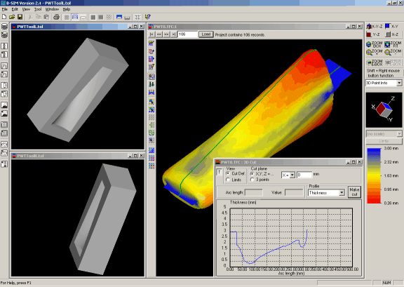
As it can be expected, the thickness varies a lot along (and also across) the product. PWT control is expected to improve the final thickness profile.
The optimization can be started immediately by clicking on Optimization / Optimize extrusion. An optimization batch is created and user is asked to confirm deleting of any previous results connected with the projects in the batch. After the confirmation, the following dialog appears, asking the user to enter optimization options:
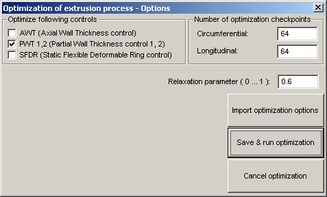
We want to optimize PWT1 and PWT2 (checked). In this case, each PWT extrusion control settings contained 32 points (time steps). For this reason, 64 longitudinal optimization checkpoints were used. For the circumferential direction, 64 checkpoints was specified, as PWT influences also the circumferential thickness profile. It should be noted here that the parison was represented by about 14,000 of elements in order to get reasonable optimization results.
The relaxation parameter is recommended to be about 0.5. Higher values cause a faster approach to the solution, however, this can lead to an "unstable" optimization, where the solution oscillates. Lower values mean a slower approach to the solution, with a better stability. In this case, we have used 0.6.
Having all the necessary values specified, the optimization starts after clicking on Save & run optimization.
B-SIM generates 10 projects for one optimization batch. Once the optimization batch is solved, you can post-process the projects to see the optimization results. In this case, the optimization took about 3 hours (P4, 1.8 GHz). The project number 4 already gives a good optimization results.
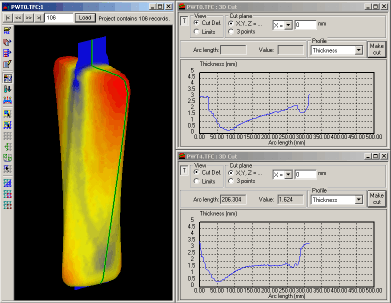
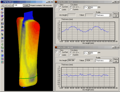
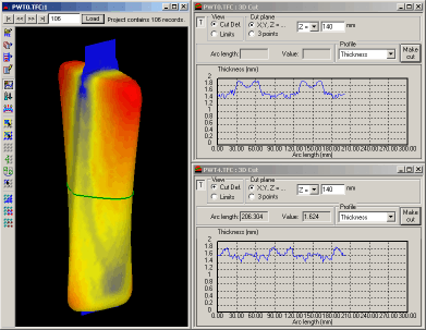
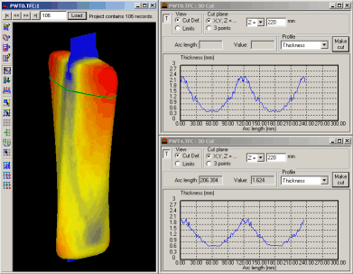
Below is a comparison of the initial results (with the uniform thickness of the extruded parison) and the optimized results (the project number 4 from the optimization batch). The limitation in PWT settings (gap stroke 1 mm) causes the final thickness is not uniform. However, the thickness distribution is better when compared with the original profile. On the following pictures, the upper graphs correspond to the initial stage, the lower graphs show the optimized thickness profiles:
Optimized PWT settings (initially, PWT settings for all time steps were 50%):
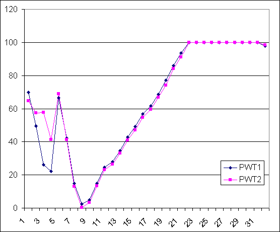
It is obvious that both PWT setting are almost identical (as the product is symmetrical). For the time indexes 23 and higher (on x axis), it can be observed that PWT setting are at their upper limit (100%) and that there is probably still a space for an optimization supposing we could afford a bigger gap stroke. Another option is to combine PWT with AWT and/or SFDR in order to get a better final thickness profile.
See also other optimization examples and details about the extrusion optimization.
