

B-SIM V2.5 Reference - Blow molding simulation

Example 2: Stretch blow molding (Bottle)
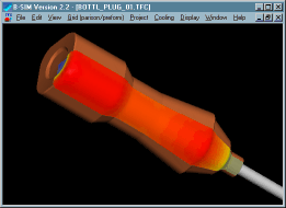
Click here to see video (111 kB).
Back to Tutorial Previous Example Next Example
Creating representation of tools
In this example there are two tools. The mold does not move, the plug is movable. Both tools are quite simple and they can be created directly in B-SIM.
Creating the mold
To create the mold just click on New Tool on B-SIM shortcuts bar, select Create new tool ('ABR" editable representation) and click OK. Create new tool representation dialog appears. Please fill in the dialog as follows:
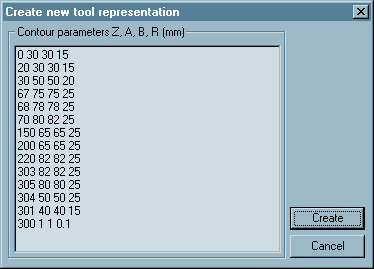 |
0 30 30 15 20 30 30 15 30 50 50 20 67 75 75 25 68 78 78 25 70 80 82 25 150 65 65 25 200 65 65 25 220 82 82 25 303 82 82 25 305 80 80 25 304 50 50 25 301 40 40 15 300 1 1 0.1 |
Each line in the dialog specifies z level of a contour, its dimensions and radius in corners. Contours are created along z axis, i.e. center of any contour is [0, 0, z].
Click Create. The following window with the new tool created appears on the screen:
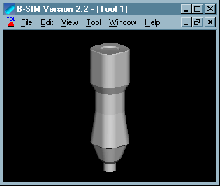
Click File / Save and save the tool (Bot_sq.tol, use "\Bottle" folder).
Creating the plug
To create the plug just click on New Tool on B-SIM shortcuts bar, select Create new tool ('ABR" editable representation) and click OK. Create new tool representation dialog appears. Please fill in the dialog with the following values:
-792 16 16 8
0 16 16 7.99
0.697245942 15.93911517 15.93911517 7.959595638
1.389185421 15.75692405 15.75692405 7.868613947
2.070552361 15.45481322 15.45481322 7.717747352
2.736161147 15.03508193 15.03508193 7.50814404
3.380946094 14.50092459 14.50092459 7.241399218
4 13.85640646 13.85640646 6.919542976
4.588611491 13.10643271 13.10643271 6.545024834
5.142300877 12.25671109 12.25671109 6.120695101
5.656854249 11.3137085 11.3137085 5.649783182
6.128355545 10.28460175 10.28460175 5.135873001
6.553216354 9.177222982 9.177222982 4.582875726
6.92820323 8 8 3.995
7.250462296 6.761892188 6.761892188 3.376719911
7.517540966 5.472322293 5.472322293 2.732740945
7.72740661 4.141104722 4.141104722 2.06796417
7.878462024 2.778370843 2.778370843 1.38744894
7.969557585 1.394491884 1.394491884 0.696374385
8 0 0 0
(Data for the rounded top of the plug were calculated using MS Excel.)
Click Create. The following window with the new tool created appears on the screen:
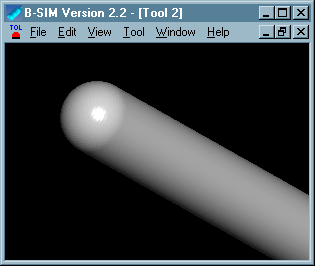
Click File / Save and save the tool (Tycka_200.tol).
Creating preform representation
In this example a simple preform is used with uniform thickness distribution. The simulated part has quarter symmetry. So it is not necessary to solve deformation of the whole preform. It is enough to create just one quarter of the preform.
To create a preform from template in B-SIM, just click on New Grid on B-SIM shortcuts bar. Create preform / parison from template dialog appears.
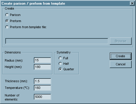
Fill in the dialog with values of radius, height, thickness, temperature and number of elements. Click Create. The following window with the new preform created appears on the screen:
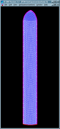
Click File / Save and save the preform (Quarter.bcs, use "\Bottle" folder).
Process control
In this case the mold does not move. The plug is used to pre-stretch the preform and then a pressure is applied to inflate the preform. So now we will create process control file to describe the plug ( tool 2) movement and the pressure applied.
Click New Process Control on B-SIM shortcuts bar. Fill in the table with the following time and pressure / position values:
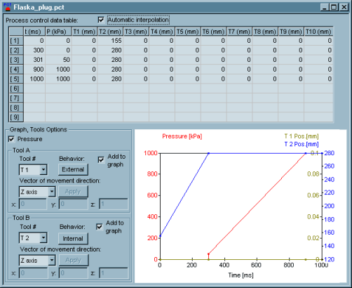
Vector of movement direction - z axis for both tools
(tool 1 and tool 2). Tool 1 is the mold - it behaves as External.
Tool 2 is the plug - it behaves as Internal. For more information see
Reference - Tool behavior.
Click File / Save and specify a file name for the process control data (Flaska_plug.pct).
Material properties
FlaskaTest.vie material is used in this example - it is a PET material:
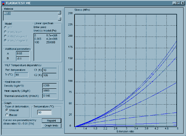
Do not modify anything in material files delivered
with B-SIM. Doing so can cause problems in simulations or incorrect
results. Calculations of material model parameters are based on complicated
stress-strain measurements. Improperly set material parameters can cause
also numerical instabilities.
For more details see Reference - Materials.
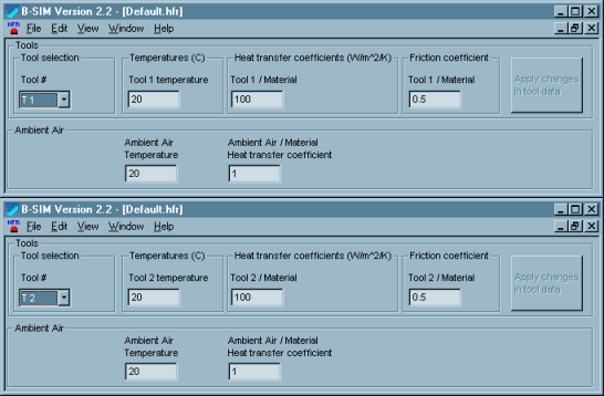
Heat and friction Click New Heat & friction on B-SIM shortcuts bar. Fill in the dialog with the following values - first select Tool1 in Tool# combo box and specify values for Tool1. Click Apply changes it tool data.
Then select Tool2 in Tool# combo box and enter values for Tool2. Click Apply changes it tool data.
Setting up the project
To set up a project click New Project on B-SIM shortcuts bar.
Use Browse buttons to select:
| Grid | Btl_00.bcs |
| Tool 1 | Bot_sq.tol |
| Tool 2 | Tycka_200.tol |
| Material | FlaskaTest.vie |
| Process control | Flaska_plug.pct |
| Heat & friction | Default.hfr |
Specify more details about this project in Additional information (optional).
Click File /Save to save the new project. Specify the project name (Bottle.tff). When the project is saved, click Project / Solve to start the project simulation. Within short time the project is solved and you can view results in post processing - just click on Project / Open for post-processing. To learn more about post processing see Reference - Post processing.
Back to Tutorial Previous Example Next Example
