
B-SIM V2.5 Reference - Blow molding simulation

Example 4: Injection blow molding

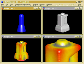
Click here to see video (130 kB).
Back to Tutorial Previous Example
Creating tool representation
In this example there is just one tool - mold. It is represented by B-SIM tool and it is quite complicated so there is no easy way to create it. CAD software (SurfCam, SolidWorks, Catia, Pro-Engineeg etc.) must be used. Once the tool is created in CAD, its STL representation can be directly imported into B-SIM.
To import STL (or DXF, Patran) tool representation into B-SIM, click New Tool on B-SIM shortcuts bar. Select format used by imported file and click OK. Now browse for the file and then click Open. The tool is automatically imported. After import click File / Save and save the imported tool into B-SIM format.
The tool used in this example is delivered with B-SIM (\Kafemlejn\kafemlejnek.tol). STL file is not distributed with B-SIM.
Creating preform
In this example the preform shape is not simple. It is necessary to create the preform using an external file with B-SIM preform template.
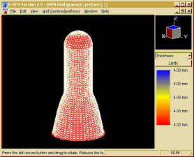
To create the preform using B-SIM template file in B-SIM, just click on New Grid on B-SIM shortcuts bar. Create preform / parison from template dialog appears. Check Preform from template file. File open dialog appears. Browse for the template file (template file Kafe.btp is delivered with B-SIM in the directory \Kafemlejn) and click Open. The following window with the new preform created appears on the screen:

Click File / Save and specify a filename (PreformRef0.bcs).
Template file description
The first line contains number of elements, symmetry and (-1). The following lines contain y, z coordinates, thickness (mm) and temperature (°C).
Data were generated using a CAD software. They define 2D curve to be
revolved around z axis.
10000 2 -1
60 0 4 160
58.96127516 5.448617357 4 160
57.91875155 10.82359826 4 160
56.84431194 16.2581338 4 160
55.74491765 21.70102012 4 160
54.62928668 27.09431738 4 160
53.47660942 32.5203512 4 160
52.30507607 37.87333017 4 160
51.08512429 43.26387565 4 160
49.81826692 48.65210846 4 160
48.4964262 54.03427375 4 160
47.1146904 59.38507862 4 160
45.65398104 64.72136022 4 160
44.10503987 70.0048511 4 160
42.42307007 75.28819169 4 160
40.59608463 80.47445234 4 160
38.53459041 85.61940283 4 160
36.24860079 90.64674016 4 160
34.00941585 95.6953163 4 160
33 101.0810436 4 160
33 106.6062181 4 160
33 112.1313927 4 160
33 117.6565673 4 160
33 123.1817418 4 160
33 128.7069164 4 160
33 134.232091 4 160
33 139.7572655 4 160
33 145.2824401 4 160
33 150.8076147 4 160
33 156.3327892 4 160
33 161.8579638 4 160
33 167.3831384 4 160
33 172.9083129 4 160
33 178.4334875 4 160
33 183.9586621 4 160
33 189.4838366 4 160
33 195.0090112 4 160
33 200.5341858 4 160
33 206.0593603 4 160
33 211.5845349 4 160
32.9324391 217.1105892 4 160
32.12076242 222.5668125 4 160
30.41036021 227.8144448 4 160
27.84979987 232.7027868 4 160
24.51183149 237.0945746 4 160
20.48459549 240.8724073 4 160
15.88826092 243.9234038 4 160
10.84279219 246.1678357 4 160
5.49952921 247.5385187 4 160
0 248 4 160
/e
Process control
In this case the tool (mold) does not move. Only a pressure is applied to inflate the preform into the mold cavity.
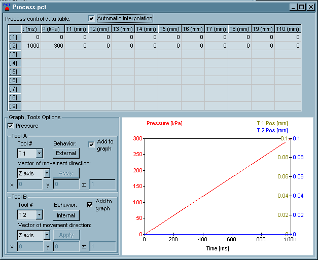
Click New Process Control on B-SIM shortcuts bar. Fill in the table with the following time and pressure values:

The mold is represented by Tool 1, behaving as external. For more information about tool behavior, see Reference - Tool behavior.
Click File / Save and specify a file name for the process control data (Process.pct).
Material properties
MatBlow.vie is used in this example. Data of this material are stored in the B-SIM material file MatBlow.vie.
Heat and friction
Click New Heat & friction on B-SIM shortcuts bar. Fill in the dialog with the following values:
Tool 1 temperature: 50C
Tool 1 HTC (heat transfer coefficient): 100 W/m^2/K
Tool 1 friction coefficient: 1
Air temperature: 25C
Air / material HTC: 5.7 W/m^2/K
Click Apply changes to tool data.
Click File / Save and specify a file name (Heat.hfr).
Setting up a project
To set up a project click New Project on B-SIM shortcuts bar.
Use Browse buttons to select:
| Grid | PreformRef0.bcs |
| Tool 1 | kafemlejnek.tol |
| Material | MatBlow.vie |
| Process control | Process.pct |
| Heat & friction | Heat.hfr |
Specify more details about this project in Additional information (optional).
Click File /Save to save the new project. Specify the project name (Project0.tff). When the project is saved, click Project / Solve to start the project simulation. Within short time the project is solved and you can view results in post processing - just click on Project / Open for post-processing. To learn more about post processing please use B-SIM context sensitive help - press F1 in B-SIM post processing window.
Back to Tutorial Previous Example
