
B-SIM V2.5 Reference - Blow molding simulation

Parison extrusion optimization
What is optimization
From B-SIM point of view, an extrusion optimization means searching for such parameters of the extrusion process control (AWT, PWT, SFDR) so that the final thickness distribution is close to uniform.
How B-SIM optimizes
B-SIM 2.45 comes with an optimization routine (option) which enables to automatically optimize AWT, PWT and SFDR. At the start of the optimization, the users can select what type of the extrusion control / what combination of controls should be optimized.
What is needed for a successful optimization
As the extrusion in B-SIM is simulated step by step and the parison continuum is approximated by a finite number of triangles, there are some problems arising, which can lead to a failure of the extrusion optimization.
Basically, three things must be fulfilled in order to get reasonable optimization results. It is necessary to have a suitable number of:
1) elements (FE representation of parison)
2) extrusion control points
3) extrusion control checkpoints
In general, the simulation results are poor when having low number of elements of FE grid. It is hard to give a "reasonable" value for the number of elements working in all cases. A suitable number of elements is also connected with the number of extrusion control points. By the "number of extrusion control points" we mean the number of points in time scale available on the extrusion equipment. Typically, 64 points can be used during one extrusion cycle. However, B-SIM does not put any limitations on the number of the extrusion control points, so it is user's responsibility to enter proper data. On the following figures, there is an explanation why the number of elements and the number of extrusion control points play a big role in the simulation of extrusion and consequently also in the extrusion optimization.
 |
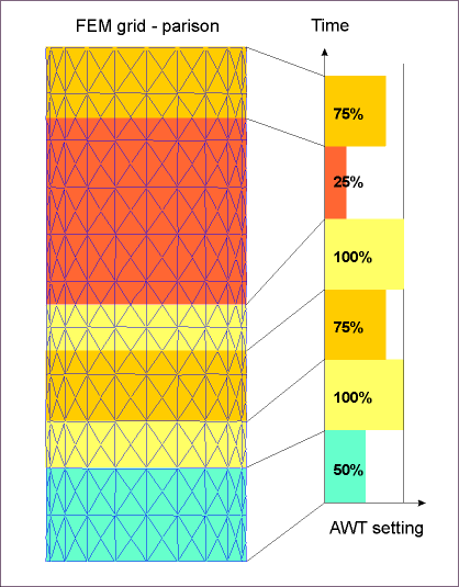
Acceptable situation Every AWT control section (rectangles with different color) contain some elements. The optimization algorithm is able to analyze how variation in AWT setting 'i' influences the thickness on parison. However, the area with AWT setting 25% contains quite large number of elements, and all these elements are influenced by one AWT setting. The optimization inside this area is limited, as all elements will get the same thickness (supposing only AWT is used). A solution is to use higher number of the extrusion control point (AWT settings) along the time axis. |
 |
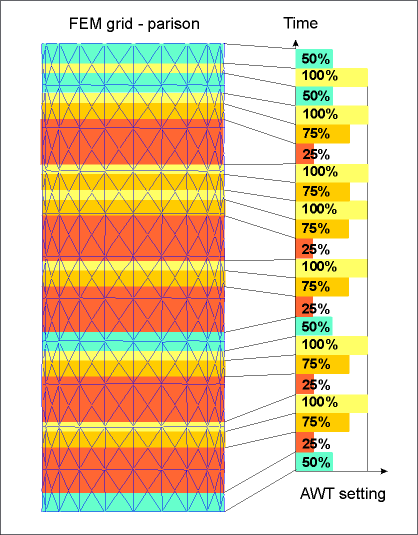
Very poor situation There is quite high number of extrusion control points, however, Some AWT control sections (rectangles with different color) have no whole elements inside. As a result, the optimization algorithm is not able to analyze how variations in AWT setting 'i' influence the thickness of the parison. B-SIM assigns one thickness value for each element. When there are more than one corresponding AWT setting for an element, the first setting is used for simulation and the rest is ignored. A solution is in increasing number of the elements on parison (refinement). |
 |
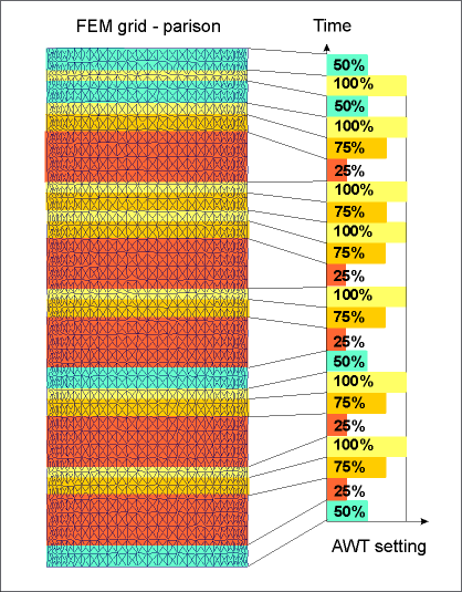
Very good situation Enough of elements and extrusion control points. This is a situation where very good optimization results can be expected supposing that the number of optimization extrusion control checkpoints is properly specified. (For details see below.) For a typical extrusion simulation project with 64 extrusion time steps in AWT (PWT) settings, the number of elements should be somewhere about 50,000 for very good results. |
The last thing is number of the extrusion checkpoints.
The extrusion checkpoint is the point where the thickness obtained by a modification of the extrusion setting is evaluated. A theoretical minimum of the checkpoints along the parison length is equal to the number of the extrusion control points in AWT(PWT) settings. A theoretical minimum of the checkpoints along the parison perimeter is not so easy to estimate as there is a linear interpolation used between SFDR settings. Anyway, B-SIM 2.45 requires the number of the checkpoints to be at least two times higher than the number of the extrusion control points (in both directions - longitudinal and circumferential). Obviously, the higher the number of the extrusion checkpoints, the better evaluation of the final thickness uniformity. However, an excessive number of control points can cause the optimization algorithm to be very slow. And, if the checkpoints fall into the same element, there is no difference in results and the whole optimization process is just slower, nothing else.
To conclude, the whole concept is simple and easy to understand and use on a daily basis. However, the B-SIM optimization algorithm cannot be used as a simple, one-click tool. It requires the user to understand what is behind the algorithm and what has to be done in order to get reasonable optimization results.
Please follow this link to see some practical optimization examples.
