T-SIM V4.5 Reference
T-SIM sheet / B-SIM preform/parison file format
This file describes grid file format for T-SIM representation
of sheets.
(Format for B-SIM representation of preforms/parisons is the same).

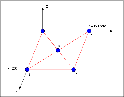
In the above figure the node 1 has coordinates ( x, y, z ) = (0, 0, 0 ). The node 4 has its coordinates ( 200, 150, 0). The numbering of the nodes within one element is counterclockwise. (First element is created by nodes 3, 1, 5).Here is the listing of corresponding file:
| T-SIM - DATA OF THE SHEET QUARTER 1 3 1 5 3.3 105.3 2 1 2 5 3.1 105.4 3 2 4 5 3.2 105.9 4 4 3 5 3.5 106.0 -111 1 1 1 1 1 1 END NOP 200.0 Char. dist 1 0.000000 0.000000 0.000000 0 2 200.000 0.000000 0.000000 0 3 0.000000 150.000 0.000000 0 4 200.00 150.000 0.000000 0 5 100.000 75.0000 0.000000 0 -111 1 1 1 1 1 1 END OF COORS 2 1 2 1 2 1 3 1 3 1 3 1 4 1 4 1 4 1 1 1 1 2 -111 1 1 1 1 1 1 END OF BCs 1 1.000000 0.000000 0.000000 0.000000 2 0.000000 1.000000 0.000000 0.000000 |
All items in the grid data file are separated by
spaces.
First line is a comment.
Second lines expresses the type of the grid symmetry. It can be FULL,
HALF or QUARTER.
In the third line begins the topology of the grid.
In each row of this part the First number is number of element. Three
other numbers indicate the nodes within the element. Fifth number is
the thickness of the element in mm. Last number in the row is the temperature
of the element in C.
List of the grid topology ends with the row -111 1 1 1 1 1 1 END NOP.
The Char. dist values is for backward compatibility
- it is the value of characteristic distance (mm) for the sheet, now
automatically calculated inside T-SIM / B-SIM code. After this row there
are data with coordinates of nodes in the following format:
n_node x y z clamp,
where n_node is the number of the node,
x, y and z are the coordinates of the node in mm,
and clamp is a flag detecting whether the node is clamped (1) or not
(0).
Coordinate part ends with row -111 1 1 1 1 1 1 END OF COORS.
Final part of the file consists of the definition of boundary conditions. Each node obeying the boundary condition is written along with the corresponding plane at which this node is bound.
The node can have one of the following status:
Free - no boundary condition (BC) is applied.
Slip along a plane - one BC is applied as a plane.
Moving along a line - two BC are applied (the line is given
by two intersecting planes).
Fixed point - three or more BC are applied.
Once a grid is created inside T-SIM/B-SIM, the boundary conditions are not editable. The possible modification of these conditions is adding / removal of clamping, but clamping is represented in the section with node coordinates. It is also possible to remove BC for any node, but once removed, the BC cannot be applied back.
When one node has to be fixed and its movement is
not allowed during the simulated process, it appears three or more times.
Such an occurrence gives the signal to solver that this node is fixed.
In this case nodes 2, 3 and 4 are fixed). Node 1 has two boundary conditions
at plane x = 0 (ref. 1) and y = 0 (ref. 2). Node 5 has no boundary condition.
The definition of the referred planes is given in last two lines of
the file:
Plane 1 has equation 1*x + 0*y + 0*z + 0 = 0.
Plane 2 has equation 0*x + 1*y + 0*z + 0 = 0.