

B-SIM V2.5 Reference - Blow molding simulation

Parison extrusion
optimization example #1
AWT control optimization
Optimized project details
In this example, a simple shape (an oval ball) is blow molded. See below the used tools and the simulation results with all AWT settings at 50% (initial, "neutral" position). No other extrusion control is used (PWT1 and PWT2 are at 50%, SFDR is at the neutral position too):
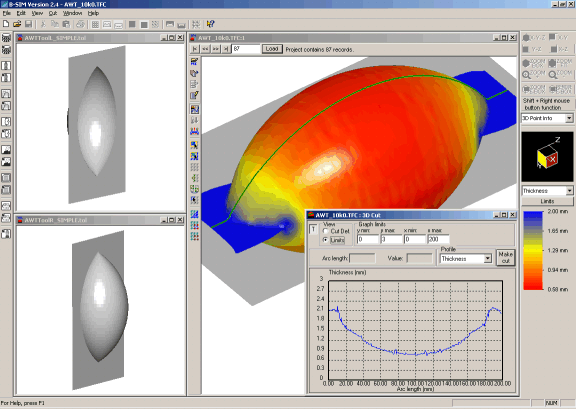
As it can be expected, the thickness is lower in the middle part of the product and higher at the ends. The product is axisymmetrical and the, AWT control is the ideal candidate for the optimization.
The optimization can be started immediately by clicking on Optimization / Optimize extrusion. An optimization batch is created and the user is asked to confirm deleting of any previous results connected with the projects in the batch. After the confirmation, the following dialog appears, asking the user to enter optimization options:
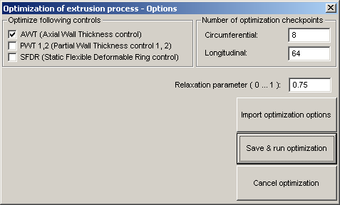
We want to optimize AWT (checked). In this case, AWT extrusion control settings contained 32 points (time steps). For this reason, 64 longitudinal optimization checkpoints were used. For the circumferential direction, 8 checkpoints is enough (as the product is axisymmetrical, and moreover, SFRD is not optimized). It should be noted here that the parison was represented by about 10,000 of elements in order to get reasonable optimization results.
The relaxation parameter is recommended to have value about 0.5. Higher values cause a faster approach to the solution, however, this can lead to an unstable optimization. Lower values means slower approach to the solution, with a better stability. In this case, we have tried 0.75 and it worked very well.
Having all the necessary values specified, the optimization starts after clicking on Save & run optimization.
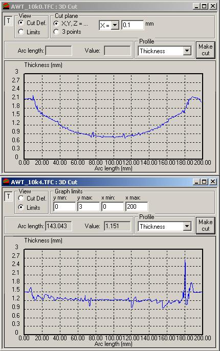
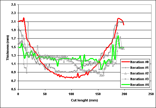
B-SIM generates 10 projects for one optimization batch. Once the optimization batch is solved, you can post-process the projects to see the optimization results. In this case, the project number 4 already gives a very good optimization. Below is a comparison of the initial results (with uniform thickness of extruded parison) and optimized results (the project number 4 from the optimization batch). As you can see, the thickness profile is almost uniform along the whole cut. The peek on the right side of the optimized thickness profile is caused by squeezed elements.
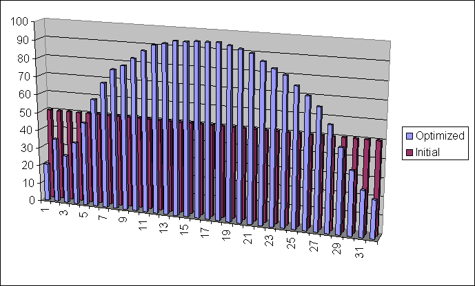
Comparison of AWT settings is here:
Finally, here is how the final thickness profile develops during the optimization:
See also other optimization examples and details about the extrusion optimization.
