T-SIM V4.5 Reference
Image distortion and pre-distortion using bitmap images (BMP, JPEG)
Images from plane, sphere or cylinder
This option allows projections of any bitmap image represented in
the following formats:
BMP, JPEG, RGB, TIFF, GIF, PNG, EMF, WMF, ICO
Multiple images can be projected. For the projection, every bitmap having its resolution higher than 1024 * 1024 is scaled to have maximum resolution 1024 * 1024.
Remark: Exactly, the imported images, before displayed, have to be converted (resampled) to have resolution 2^m * 2^n, where m, n are in the range 0 ... 10.
This document contains information about
Projection
of a new image (bitmap)
To project a new image, open a solved project for post-processing. From
post-processing menu, select View / Image mode. Image manager bar appears
on the right side. Click on the icon with tool tip "Add new texture"
(the topmost icon with green rectangle and yellow small star):
Windows File Open dialog appears. Now, browse for the image (bitmap) to project. Currently, BMP, JPEG, RGB, TIFF, GIF, PNG, EMF, WMF, ICO formats are supported. Once the image is selected, click Open.
Depending on the projection method (from plane [default], sphere or cylinder), light red and yellow box, part of a sphere or part of a cylinder are displayed around the formed product.
Now, change the projection type which will be used (this can be changed anytime until you press Apply button):
Select rectangle, sphere or cylinder depending on the projection method to be used. Use the edit boxes on the Image manager bar to change position and rotation of the plane / sphere / cylinder, and specify the additional parameters:
Projection from plane
Projection from sphere
Projection from cylinder
Editing
projection definition of a projected image (bitmap)
Once an image is projected, its projection definition can be repeatedly
edited.
Select an image in the image list of the Image manager bar
and click on Edit button. Now it is possible to modify
type of projection, projection parameters and source image file name.
For details see Projection of a new image.
Once the projection definition is modified, click on Apply button. The
projection procedure starts and after some time the modified projected
image is displayed.
Removing
and flipping projected image(s)
To remove image(s):
Select one or more images in the image list of the Image manager bar
and click on the icon with toot tip "Remove selected texture(s)":
Message box with the following warning appears: Selected images will be removed. Click Yes to remove the images, click No or Cancel to leave the images projected.
To flip image(s) vertically
/ horizontally:
Select one or more images in the image list of the Image manager
bar and click on the icon with tool tip "Flip selected texture(s)
vertically" or "Flip selected texture(s) horizontally":
Selected image(s) will be automatically flipped. The flipping operation can be repeated in both directions (vertically and horizontally).
Saving and loading definitions of projections
To save definitions of all projections, click on the
icon with tool tip "Save definitions...". Specify projection
definition file name and click Save.
To load definitions of all projections, click on the icon with tool
tip "Load definitions...". Specify projection definition file
name and click Open. The projection definition file is loaded, all the
projections stored in it are automatically re-projected and displayed
on the screen.

When images are projected, select the first record of the simulated project
and load it (enter 1 in the record bar edit box and click on Load button). The projected image(s) will be automatically pre-distorted. Now, to export the pre-distorted picture to bitmap, click on the icon with tool tip "Export high resolution image (BMP/JPEG/PNG/GIF)":
![]()
Remark: The exporting routine was completelly rewritten
to provide high resolution images suitable for high quality printing.
The new routine is implemented in T-SIM from version 4.45 release 3.
The following dialog appears:
First, click Browse button and in the Windows Save dialog, specify the image file name and select the required image file format. Currently, export to BMP, JPEG, PNG, TIFF and GIF is supported:
Confirm you input in the Save dialog by clicking on Save button...
Now, in the Image export options dialog, specify the required final image width in pixels. A corresponding DPI value is calculated automatically:
Enter also the exported sheet area ( minimal and maximal x and y coordinatest). The initial values cover the whole sheet. However, it is possible to specify any sheet area. This enables export of high resolution images covering just small final product areas.
The maximal resolution of an image exported using this routine is 4096 * 4096 pixels. If you need higher resolution, use image subtivision. In both direction, every image cen be divided up to 10 subimages. This means that maximum resolution for the exported area is 40960 * 40960 pixel. If this is not enough, you would have to export sheet subareas manually.
Click Export to create image(s).
When you get a message saying "Please enter an integer between 100 and 4096.", increase the image subdivision to get higher upper limit for resolution. For example when Image width is 6000 and Image subdivision in X is 1, increase the image subdivision to 2. The upper resolution limit is now 8192.
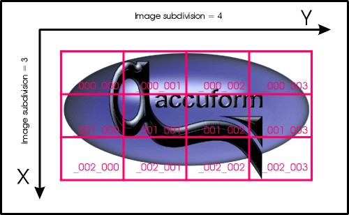
After export, T-SIM gives a message about the result. If the image subdivision was 1 in both direction, just one image is created, having name as specified in the Image Export Options dialog. If the image subdivision is greated than 1, multiple images are created, each with an extension in its name in for _iii_jjj (_000_000, _000_001 ... ), in order to distinguish between subimages:
Remark: This export works also for images projected using VRML files.