
B-SIM V2.5 Reference - Blow molding simulation

Parison / preform representation
Parison or preform in B-SIM is represented using a finite elements mesh with thickness and temperature data. Each element has its own thickness and temperature. The parison / preform representation is created directly in B-SIM using a simple dialog. Once a parison / preform is created, thickness and / or temperature of every element can by changed. The finite elements grid can be also refined when open in B-SIM Grid view. However, refinements from post-processing are more advanced - see Refinement from post-processing.
- Creation / Import
- Modification of temperature profile
- Modification of thickness profile
- Modification of thickness & temperature profile using external data
- Modification of thickness using template
- Modification to elliptical using template
- Refinement
- Modify boundary conditions
- Clamping
- Specify areas where no pressure is applied
- Using multiple materials for extruded parison
Creation / import of parison / preform
A new parison / preform FE (Finite Elements) grid can be created directly in B-SIM (axisymmetrical shapes). Preforms can created also from a template file (more complicated, but still axisymmetrical shapes).
General preform shapes (for injection/stretch blow molding) can be imported from Ansys and STL files. It is supposed the imported file contain FE grid (shell elements - triangles), and the grid is without holes.
There is also a possibility to import 3D grid (outer and inner surface represented by triangles). B-SIM converts this grid to a new shell elements grid, including evaluation of the thickness (calculated as the distance between outer and inner surface). This feature is implemented in B-SIM from version 2.45, release 3.
The last option is to create shrink sleeve. The created shrink sleeve can be used to simulate sleeve shrinkage process and predict the preprinted image distortion / predistortion. The shrink sleve is idnetical with parison, except the boundary conditions. It is supposed the sleeve can "slide" on its lower edge. No nodes are fixed.
Parison, preform created directly in B-SIM
The parison / preform of cylindrical shape can be created within B-SIM when using the built-in editor. The result of this editor is a text file which holds the geometrical and topological data of the parison / preform. The parison / preform is oriented in the direction of z axis before the inflation.
To create a new parison / preform representation, click on the icon with the tool tip "New grid" on B-SIM shortcut bar or click on File / New and select B-SIM Grid (parison / preform) as the document type and click OK.
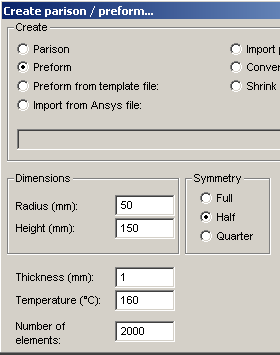
The following dialog appears:

In the dialog box the following items have to be specified:
- What should be created - parison, preform etc. In this case, select parison or preform.
- Dimensions, thickness and temperature.
- Number of elements.
- Type of symmetry:
Full - without plane of symmetry
Half - one plane of symmetry ; plane x = const.
Quarter - two planes of symmetry : x = const1, y = const2.
Once all the items are specified, click Create. The parison / preform representation is automatically created and opened for further modifications.
Parison vs. preform - definition in B-SIM
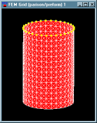
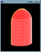
Parison is open on two sides and is used for extrusion blow molding simulations. Preform is open just on one side and is used for injection / stretch blow molding:
 |
 |
 |
 |
Preform created from template file
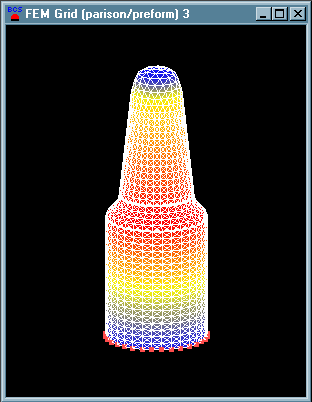
More complicated preform can be created from a template file. All data needed are stored in the file - no additional data has to be specified. Just use Browse button to select the template file (*.btp). Then click on Create. The preform is automatically created and opened for further modifications.
Template file format
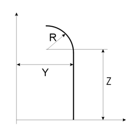
The first line contains number of elements, symmetry (0 - quarter, 1 - half,
2 - full, 3- stripe) and (-1). The next rows contain y, z coordinates, thickness
(mm) and temperature (°C).
From B-SIM Version 2.22, "R" can be used at the beginning of any row to indicate a radius should be created:
R 9 20 100 5 160 ... a radius 9 mm will be created at y = 20 mm, z = 100 mm. Thickness will be 5 mm and temperature 160 °C.
|
(Sample file: preform.btp) |
 |
ANSYS and STL import (shell elements grid import)
Complicated preform shapes can be imported from ANSYS and STL files. It is supposed the imported file contain FE grid (shell elements - triangles), and the grid is without holes. All elements have zero thickness after import and it is the user's responsibility to modify the thickness (and temperature) before using the preform grid in simulation).
ANSYS import routine expects ANSYS file with blocks EBLOCK / NBLOCK. STL import can read both binary and text files.
Import of 3D preform (outer/inner surface)
Complicated preform shapes represented by 3D outer and inner surface can be imported from the following files: STL, DXF, B-SIM tool (TOL), VRML, Patran, HYPERMESH ASCII.
The importing routine reads the file(s) and converts the imported data to outer and inner FE grid. Having the outer and inner surface, a new mesh is created in between those surfaces.
Below is a short description how to import 3D grid and convert it to shell elements grid.
In the Create parison / preform dialog, click on Convert 3D preform to B-SIM grid.:

Immediately, the following dialog appears:

Browse for the file to import. If you have two files to represent outer and inner surface separately, click on Two files and browse for the files. You can specify also the required number of elements, however, B-SIM can estimate an appropriate value for you automatically. Then click Import. B-SIM reads the file(s) and generates a new grid. If anything fails, B-SIM gives a message and hints how to solve the problem. See more details in the section Importing 3D preform import - Requirements and details.
Modification of temperature profile
To edit the temperature profile of an existing preform / parison, open it in B-SIM Grid view - click on the icon with the tool tip "Open grid" and in Windows File Open dialog, browse for the preform / parison file. Once the file is selected, click Open. A new window with the picture of the selected preform / parison appears.
Now, click Grid / Edit temperature to change the preform / parison temperature inside a selected rectangular area. Then move the cursor into a required position and press and hold down the left mouse button. Move the cursor to the second corner of the rectangle and release the mouse button.
The following dialog appears asking for value of the new temperature:
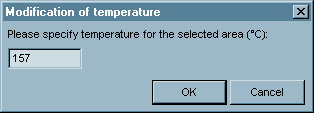
Specify the value and click OK to modify the temperature inside the area selected. To cancel the procedure of the modification of temperature, click Cancel.
If the temperature profile is changed, the preform / parison document
is marked as modified. When closing this document, B-SIM displays a warning
offering to save the modified preform / parison under a new name (i.e. Windows
File Save as dialog appears).
Before closing B-SIM Grid view, the modified preform
/ parison can be saved also using File / Save (or File / Save as) command.
Modification of thickness profile
To edit the thickness profile of an existing preform / parison, open it in B-SIM Grid view - click on the icon with the tool tip "Open grid" and in Windows File Open dialog, browse for the preform / parison file. Once the file is selected, click Open. A new window with the picture of the selected preform / parison appears.
Now, click Grid / Edit thickness to change the preform / parison thickness inside a selected rectangular area. Then move the cursor into a required position and press and hold down the left mouse button. Move the cursor to the second corner of the rectangle and release the mouse button.
The following dialog appears asking for value of the new thickness:
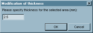
Specify the value and click OK to modify the thickness inside the area selected. To cancel the procedure of the modification of thickness, click Cancel.
If the thickness profile is changed, the preform / parison document
is marked as modified. When closing this document, B-SIM displays a warning
offering to save the modified preform / parison under a new name (i.e. Windows
File Save as dialog appears).
Before closing B-SIM Grid view, the modified preform
/ parison can be saved also using File / Save (or File / Save as) command.
Modification of thickness & temperature using external data
To modify the temperature & thickness profile of an existing preform / parison using user-specified external data, open the parison / preform in B-SIM Grid view - click on the icon with the tool tip "Open grid" and in Windows File Open dialog, browse for the preform / parison file. Once the file is selected, click Open. A new window with the picture of the selected preform / parison appears. Now, select command Modify thickness & temperature profile. The following dialog appears:

Now, fill in the temperature / thickness profile data. On every line there must be 15 values - height, 13 temperatures and thickness at given location.

Here is an example of height / temperature / thickness profile input:
| 100 | 150 | 149 | 148 | 148 | 147 | 147 | 147 | 147 | 147 | 148 | 148 | 149 | 150 | 2.5 |
| 75 | 149 | 148 | 147 | 147 | 146 | 145 | 145 | 145 | 145 | 146 | 146 | 147 | 149 | 2.4 |
| 50 | 148 | 147 | 146 | 146 | 145 | 144 | 144 | 144 | 144 | 145 | 145 | 146 | 148 | 2.2 |
| 25 | 149 | 148 | 147 | 147 | 146 | 145 | 145 | 145 | 145 | 146 | 146 | 147 | 149 | 2.3 |
| 0 | 149 | 148 | 147 | 147 | 146 | 145 | 145 | 145 | 145 | 146 | 146 | 147 | 149 | 2.35 |
Modification of thickness using template
Modification of thickness using template enables to quickly modify parison thickness profile by specifying just four numbers - thicknesses - at given parison points T0, T1, T2 and T3:
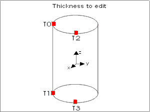
Between these four points, the thickness is calculated using linear approximation.
To modify thickness using template, open an existing parison grid in B-SIM Grid view - click on the icon with the tool tip "Open grid" and in Windows File Open dialog, browse for the preform / parison file. Once the file is selected, click Open. A new window with the picture of the selected preform / parison appears.
Click on Grid / Modify thickness. The following dialog appears asking for values T0 ... T3:

Enter these values (0.5, 1.5, 0.7, 1.8 in this case) and click OK. Parison thickness is automatically modified:

If the thickness profile is changed, the preform / parison document
is marked as modified. When closing this document, B-SIM displays a warning
offering to save the modified preform / parison under a new name (i.e. Windows
File Save as dialog appears).
Before closing B-SIM Grid view, the modified preform
/ parison can be saved also using File / Save (or File / Save as) command.
Modification to elliptical using template
B-SIM enables to modify a parison (with circular cross-section) to parison with elliptical cross-sections. Only four numbers must be specified - A top, B top, and A bottom, B bottom - dimensions of upper and lower ellipses. Between these two ellipses there is a connecting surface calculated using linear approximation:

To modify parison shape to elliptical, open an existing parison grid in B-SIM Grid view - click on the icon with the tool tip "Open grid" and in Windows File Open dialog, browse for the preform / parison file. Once the file is selected, click Open. A new window with the picture of the selected preform / parison appears.
Click on Grid / Modify to elliptical. The following dialog appears asking for values A top, B top, A bottom and B bottom:

Specify these values (20, 20, 60, 60 in this case) and click OK. Parison shape is automatically modified:

If the parison shape is changed, the parison document is marked
as modified. When closing this document, B-SIM displays a warning offering to
save the modified parison under a new name (i.e. Windows File Save as dialog
appears).
Before closing B-SIM Grid view, the modified parison
can be saved also using File / Save (or File / Save as) command.
Grid refinement
To refine an existing preform / parison grid, open the preform / parison in B-SIM Grid view - click on the icon with the tool tip "Open grid" and in Windows File Open dialog, browse for the preform / parison file. Once the file is selected, click Open. A new window with the picture of the selected preform / parison appears.
Click Grid / Refine to refine the preform / parison inside a selected rectangular area. Then move the cursor into a required position and press and hold down the left mouse button. Move the cursor to the second corner of the rectangle and release the mouse button. The preform / parison is automatically refined.
The refinement in B-SIM Grid view is an old-fashioned way how to increase the preform / parison grid density in selected areas. There is no connection with the deformation of every element during the simulation of the molding process. It is hard to refine the areas of the preform / parison (before molding) where the density of grid is not high enough after molding. For this reason, more sophisticated ways of refinement are implemented in B-SIM - see Refinement from post-processing.
Modification of boundary conditions
To remove boundary condition applied on nodes, open a parison/preform in B-SIM Grid view - click on the icon with the tool tip "Open grid (parison/preform)" and in Windows File Open dialog, browse for the file. Once the file is selected, click Open. A new window with the picture of the selected parison/preform appears.
Click on Grid / Boundaries / Remove boundaries. Then move the cursor into a required position and press and hold down the left mouse button. Move the cursor to the second corner of the rectangle and release the mouse button. The boundary conditions are immediately removed inside the area selected. Save the parison/preform.
Remark: At this moment, it is not possible to add boundary condition to nodes (except Clamping).
ClampingClamping in B-SIM is understood as a fixation of preform / parison grid nodes. It means that the clamped nodes cannot move in any direction. Any clamped node can be made free from its constrains and any node can be clamped. Fixed nodes (fixed nodes are not clamped nodes) cannot be made free from their constrains. Also nodes with boundary conditions cannot be made free from their boundary constrains. See also Nodes and their boundary conditions.
The area for clamping is selected "by hand".
To modify clamping on an existing preform / parison, open it in B-SIM Grid view - click on the icon with the tool tip "Open grid" and in Windows File Open dialog, browse for the preform / parison file. Once the file is selected, click Open. A new window with the picture of the selected preform / parison appears.
Click on Grid / Clamping. The following commands are accessible in the Clamping submenu:
- Use the commands 1,2,3 or 4 to add a new clamping inside / outside an area selected.
- Use the command 5 to remove the preform / parison clamping within an area selected.
Commands 1-4:
Select required command and click it. Then move the cursor into a required position
and press and hold down the left mouse button. Move the cursor to the second
corner of the rectangle / ellipse and release the mouse button. The clamping
is immediately added inside / outside the area selected or removed inside the
area selected (the operation performed depends on the selected command).
Command 5:
Click on this command and click it. Then move the cursor into a required position
and press and hold down the left mouse button. Move the cursor to the second
corner of the rectangle / ellipse and release the mouse button. The clamping
is immediately removed inside the the area selected.
In order to successfully simulate extrusion blow molding, where some areas of an extruded parison are outside a mold after it is closed, B-SIM enables to specify parison areas with "no pressure" condition. If an area has assigned "no pressure" condition, no pressure will be applied on it during the molding process simulation. As a result, B-SIM simulation will remain stable.
Areas with "no pressure" condition can be created very easily using the following two commands from No pressure areas submenu located under Grid menu:
Create within rectangle
Click this command. Then move the cursor into a required position and press
and hold down the left mouse button. Move the cursor to the second corner of
the rectangle and release the mouse button. "No pressure" condition
is immediately applied inside the area selected. All nodes within the selected
rectangle are marked to be included in the "no pressure" area (even
the nodes currently invisible). To force B-SIM to select only visible nodes,
press and hold the ALT key during the rectangular area selection.
Any node inside an area with "no pressure" condition is marked by
white point.
To remove "no pressure" condition on a rectangular area, click on Remove within rectangle command. Then move the cursor into a required position and press and hold down the left mouse button. Move the cursor to the second corner of the rectangle and release the mouse button. "No pressure" condition is immediately removed inside the area selected. All nodes inside the selected area are used (even the invisible). To force B-SIM to select only visible nodes, press and hold the ALT key during the rectangular area selection.
Multiple materials on extruded parisonB-SIM supports up to five different materials to be used on one FE grid (parison).
Materials can be associated with FE grid elements using a simple procedure. Every element has its material group number 1..5 (default is 1). The real material corresponding to a material group is assigned in B-SIM project.
To associate elements with a material group, open an existing parison, click Material / Create material group area. Then move the cursor into a required position and press and hold down the left mouse button. Move the cursor to the second corner of the rectangle / ellipse and release the mouse button.
The following dialog appears:

Select the required material group and click OK. To display the actual distribution of material group on parison, select Material on B-SIM Scale tool bar.
B-SIM Grid viewB-SIM Grid view is a window enabling to display and perform modifications of preforms / parisons (represented by B-SIM Grids). A preform / parison is displayed in B-SIM Grid view after creation or after opening.
To open the preform / parison - click on the icon with the tool tip "Open grid" and in Windows File Open dialog, browse for the preform / parison file. Once the file is selected, click Open. A new window with the picture of the selected preform / parison appears.
B-SIM Grid view allows to:
- Rotate, zoom and pan the displayed preform / parison
- Display thickness and temperature profiles on the preform / parison
- Visualize nodes with different boundary conditions
- Explore the preform / parison thickness and temperature at different areas
- Modify thickness, temperature
- Refine preform / parison grid
- Modify clamping of the preform / parison
- Display properties of the preform / parison - click on Grid / Properties. The following dialog appears with general information about the open preform / parison:

